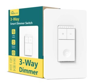
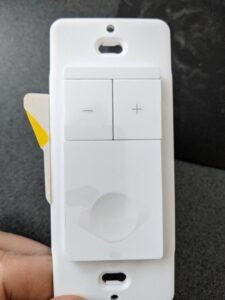
Without enough research I ordered a TreatLife Smart Dimmer switch from Amazon. I like the fact that it had an on/off button and separate dimming buttons along with some LED’s that show the setting.
I also like the fact that it had an ESP8266 mcu which meant that it should be reprogrammable.
When it arrived I discovered a few things:
- It is rated for 110V not 240V like in Australia
- It obviously has no Australian RCM approval

Looking For the Silver Lining
Ok, I can’t use it for its real purpose but before throwing it into the bin lets see what could be useful:
- The switch has an ESP8266 MCU which can be reprogrammed.
- Apparently the switch has 2 mcu’s. The ESP8266 is used to gain access to the network and it also has a special MCU that would communicate with the rest of the hardware which uses Tuya. ESPHome supports communicating with a Tuya MCU.
- It has nice buttons and the led display
Investigation
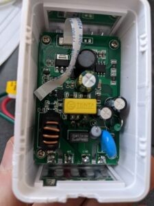
A couple of screws later I unclipped the back which contains the high voltage circuit. This is connected via a ribbon cable to the low voltage circuit that contains the LED’s, buttons and MCU’s.
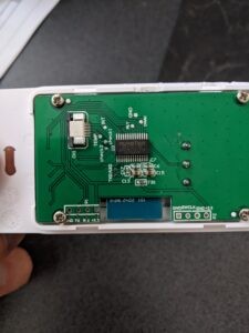
The low voltage PCB has the Tuya MCU on one side and an ESP8266 on the other side. Most of the stuff there is connected to the Tuya MCU so we should be able to control that from the reprogrammed ESP8266. Lets just hope the Tuya MCU doesn’t notice that the other PCB is no longer connected.
What is also nice is that the pins of the ESP are exposed onto points near the edge of the PCB so I could either solder on a header or get away with just pressing an FTDI cable to them to perform the initial reflashing. Future flashes would be done OTA.
Potential Issues
Power
The board needs a 3.3V power source. This could be provided by a battery or dedicated power source.
A battery could be used but some creativity would be needed to be efficient. The ESP8266 is capable of deep sleep but I’m unsure about the Tuya MCU and we would still need to react quickly to a button press which is handled by the Tuya MCU. It may be possible to instruct the Tuya MCU to go to sleep, wake with a button press and in turn wake up the ESP8266 but that will depend on how its been wired up.
A dedicated power source in the form of a cheap phone charger could provide power if a port is added to the board.


Comments