I am fortunate enough to have a garage big enough to take two cars. The garage has an automatic door that can be triggered either through a door bell button or through a key fob via RF. Lets see how we can make things a bit smarter.
Aim
I would like to achieve the following:
- Detect when a car is present
- Detect if the garage door is open or closed
- Be able to trigger the garage door computationally
Investigation
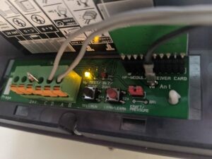
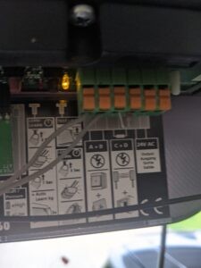
The Garage Door Controller is attached to the roof. I removed the front and took a couple of pictures of the circuit board inside.
The wall switch is attached to the terminal pins A and B. Shorting them will trigger the door to open or close.
I presume the resistor is there to provide a pull-up that would otherwise block the door triggering. You could connect a sensor that would detect if an object is in the way of the door closing but here the resistor just provides a closed circuit all the time.
The 24V and Ground terminals will be useful to provide power.
There is also plenty of space to mount a small board inside.
The Brains
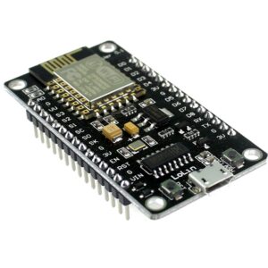
An esp8266 mcu will be used to control everything. It needs 3.3V though I can use 5V since it is on a dev board that has its own linear regulator. It has plenty of spare GPIO’s and can connect to WIFI. It can be flashed with ESPHome which means very little actual coding is required.
The 24V from the garage door controller can be used to power it by passing that through a 5V buck regulator. AliExpress has some for 70c each but I had some spare Pololu ones that are massively overkill for the project.
This device will connect to my home automation software, Home Assistant, which is already supported by ESPHome, and will expose its sensors and outputs to it.
Detect Car Presence
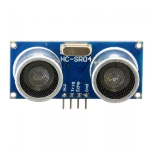
Car presence can be detected by mounting an ultrasonic sensor above each of their spots and measuring the distance down. The HC-S04 is powered by 5V and can be triggered by raising the trigger pin with 3.3V. Its response will be 5V so this will need to pass through a voltage divider to bring it down to 3.3V for the MCU.
A sensor for each car will mean using 4 GPIO’s on the MCU to trigger and receive the response. I could probably get away with 3 (1 shared trigger, 2 responses) but there are plenty spare.
Garage Door State
The door state can be provided using a magnetic switch connected to the back of the door and a convenient fixed location. The GPIO it is connected to will need its internal resistor configured to pull-down with it going active when the magnet is close.

Trigger Garage Door
Triggering the garage door should be as simple as connecting a GPIO to the where the existing switch connects to the Garage Controller. This can just be done in parallel with the exiting hardware switch since we don’t really care about detecting if someone is pressing a switch but another option would be to wire the switch to one of the GPIO’s and then pass that on to the door.
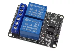
For safety I will actually use a relay to close the switch circuit. The pictured one has two relays but we only need one, I just like the board as it also has an optocoupler if proper isolation is needed.
To Be Continued
Stay tuned for the next part
Comments